Content from: https://habr.com/en/post/441050/
Hi everyone!
Winter has arrived, and so I had to check the thermal insulation of my out of town residence dacha. And it just turned out a famous Chinese marketplace started to sell cheap thermal camera modules. So I decided to DIY it up and build a rather exotic and useful thing — a heat visor for the home. Why not? Especially since I had a Raspberry Pi lying around anyway… The result is down below.
here), but neither worked out of the box for me.
Advanced Pythonists could theoretically write their own controller driver. The datasheet explains how to extract a frame out of it. But you’ll have to describe all the calibration procedures manually, which I find excessively hard. So I used option 2. It turned out to be a bit convoluted, but still manageable.
Thanks to Chinese ingenuity (or luck), the output configuration on the board turned out to be very convenient: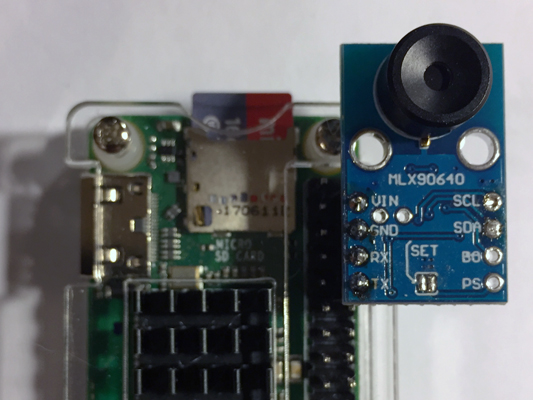
All I needed to do was to insert the board into Raspberry’s port. The board has a 5V-3V converter built in, so the delicate Rx and Tx outputs of the Pi aren’t in any danger.
I’d also add that you could connect it similarly while using option 1, but you’ll have to be extremely careful and proficient in soldering. The board has to be mounted on the other side of the Pi (example is in the header photo).
Software
The famous Chinese marketplace offers this majestic piece of software for accessing the GY-MCU90640: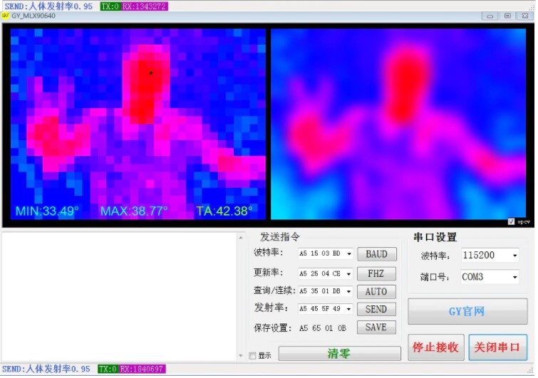
Apparently there also has to be some description of the communication protocol used to access the microcontroller, and after a short chat with the seller (big respect to him), I had said protocol in my hands. In PDF and in pure, distilled Chinese.
Thanks to Google Translate and a healthy dose of copy-pasting, around 90 minutes later the protocol has been decoded. I uploaded it on GitHub. Turned out that the board understand 6 basic commands, including one for requesting the current frame via a COM port.
Every pixel of the matrix is essentially a reading of the object’s temperature. The temperature value is in degrees Celsius multiplied by 100 (a 2-byte number). There’s even a special mode when the board sends frames to the Pi automatically 4 times per second.
The full script for receiving thermal images:
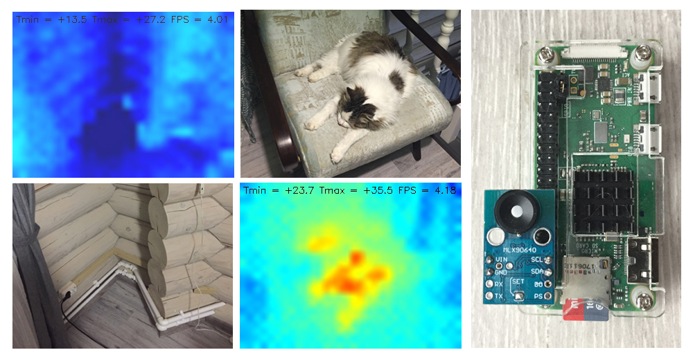
Results
The script polls the thermal matrix and outputs frames to the connected monitor’s console, 4 times per second, which is enough to not experience too much discomfort. For visualization it uses the OpenCV package. When you press S, “heat maps” from the camera are uploaded as JPGs to the script’s folder.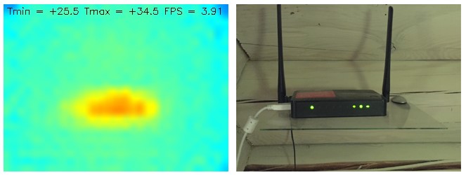
For better viewability I also made the app display minimum and maximum temperature within the frame. So, by looking at the heat map we can estimate the temperature of the coldest and hottest objects (within a degree, usually on the higher side), within the range of 20-40 degrees. Ctrl+C exits the script.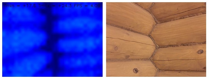
The script works the same on the Raspberry Pi Zero W and Pi 3 B+. I installed a VNC server on my smartphone, so, by carrying a Pi connected to a power bank with a VNC-enabled smartphone we can get a pocket thermal camera that saves images. Might not be too convenient, but it does the job.
After the first boot it might display the maximum temperature incorrectly, in which case just rebooting the script should do the job.
That’s about it for today. The experiment could be considered a success. You can definitely do a thermal scan of a house using this device. If someone can come up with other uses for this, please write in the comments.
Happy work week and see you soon!
UPD: I was asked in the comments to take a shot of the house from the outside. Here it is. The pictures ended up not very informative due to lower contrast of temperatures. The two upper photos are the entire house from two angles. The two lower photos are different windows.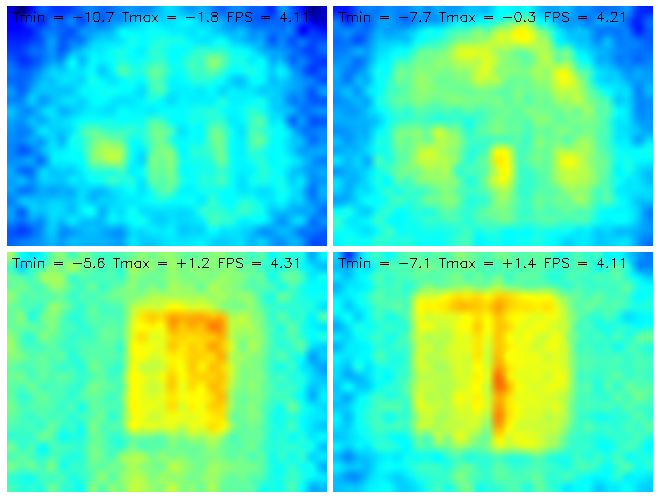
The only change I made to the code was the temperature range: from +20...+40 to -10…+5
ความคิดเห็น
ยังไม่มีความคิดเห็น
แสดงความเห็น